In this article, I will explain the key difference between multiplexer and demultiplexer. The multiplexer and demultiplexer are widely used combinational logic circuits in digital electronics. The primary difference between a multiplexer and a demultiplexer is that the multiplexer accepts signals from various input lines and selects and sends one of them to the output line, whereas the demultiplexer accepts only one input signal and distributes it over multiple output lines.
Before discussing the differences between multiplexer and demultiplexer. Let us first get an overview of multiplexers and demultiplexers individually.
What is a Multiplexer?
In digital electronics, the multiplexer is a combinational logic circuit that accepts digital information from various sources and sends the selected information to the output line.
It is also termed as MUX. Since the multiplexer performs the function of selecting specific data or information from multiple sources. Hence, it is also called a data selector.
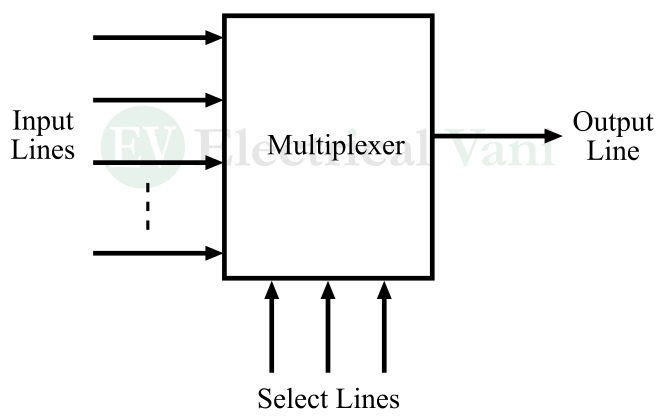
A multiplexer typically has multiple input lines and a single data output line as shown in the block diagram of multiplexer.
The multiplexer operates on a many-to-one operating principle, which means it processes information from many sources into a single source.
The operation that a multiplexer performs is called multiplexing which is used in data communication in digital systems.
Multiplexers are used in various applications such as telecommunication networks, control systems, digital communication systems, computer networks, and more.
What is a Demultiplexer?
A demultiplexer is also a combinational logic circuit in digital electronics that is used to perform the reverse operation of the multiplexer. It is also termed De-MUX.
A demultiplexer accepts a digital signal and distributes it over multiple output lines. Hence, it is also called a data distributor.
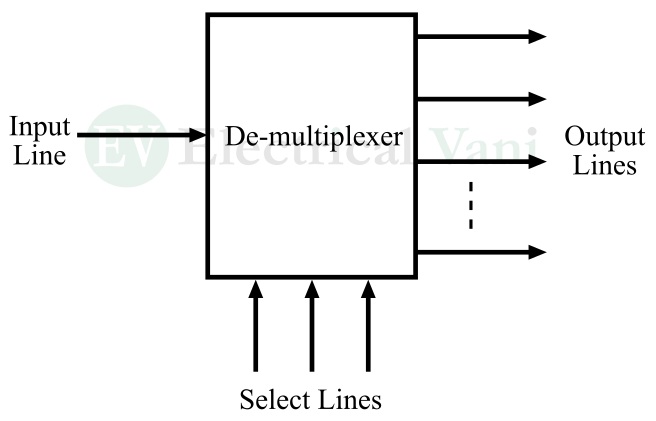
A multiplexer has a single input line and multiple output lines as depicted in the block diagram of the demultiplexer.
It works on the one-to-many operating principle, which means it processes digital information received from one source into many sources.
Demultiplexers are used in various applications such as communication systems, arithmetic logic units, telecommunication and computer networks, etc.
Let us now discuss the key differences between multiplexers and demultiplexers.
Difference between Multiplexer and Demultiplexer
The important differences between multiplexer and demultiplexer are listed in the following table:
| Key |
Multiplexer |
Demultiplexer |
| Basic | A multiplexer is a digital circuit used to process digital information from multiple sources into a single source. | A demultiplexer is a digital circuit used to process digital information from a single source into multiple sources. |
| Alternate name | Multiplexer is also termed as “MUX”. | Demultiplexer is also termed “De-MUX”. |
| Function | Multiplexer receives multiple digital signals and selects one of them to send over the output line. | Demultiplexer receives a single digital signal and distributes it over multiple output lines. |
| Act as | Multiplexer acts as a data selector. | Demultiplexer acts as a data distributor. |
| Working principle | Multiplexer operates on the principle of many-to-one. | Demultiplexer operates on the principle of one-to-many. |
| Process | The process that a multiplexer does is called multiplexing. | The process that a demultiplexer does is called de-multiplexing. |
| Construction | A multiplexer has 2n input lines, n-select lines, and 1 output line. | A demultiplexer has 1 input line, n select lines, and 2n output lines. |
| Signal conversion | A multiplexer converts a parallel signal into a serial signal. | A demultiplexer converts a serial signal into a parallel signal. |
| Types | Multiplexers can be of various types depending on the input lines, such as 4-to-1 multiplexer, 8-to-1 multiplexer, 16-to-1 multiplexer, 32-to-1 multiplexer, and more. | Demultiplexers can also be of various types depending on output lines, such as 1-to-2 demultiplexer, 1-to-4 demultiplexer, 1-to-8 demultiplexer, etc. |
| Location in the digital system | The multiplexer is usually placed at the transmission end of the system. | Demultiplexer is placed at the receiver end of the system. |
| Applications | Multiplexer is used in communication systems, telephone and computer networks, and control systems to perform multiplexing. | Demultiplexer is also used in communication systems, computer networks, arithmetic logic units, etc. to perform de-multiplexing of signals. |
Conclusion
In conclusion, multiplexers and demultiplexers are two crucial combinational logic circuits in digital electronics. The multiplexer is used to select a particular signal from multiple signals, whereas the demultiplexer is used to distribute a single data over multiple output lines. Both MUX and De-MUX are important circuits in communication systems and computer networks.
In this article, I have listed all the key difference between multiplexer and demultiplexer along with their basic introduction. If you have any queries related to this topic. Please let me know in the comment section, and I will answer shortly.