In this article, we will derive the EMF Equation of Transformer. The EMF equation of an electrical transformer is a mathematical expression that provides the value of EMF induced in the primary and secondary windings of the transformer at a specified frequency.
EMF Equation of Transformer Derivation
Let us consider an electrical transformer with the following parameters and whose block diagram is shown in the following figure.
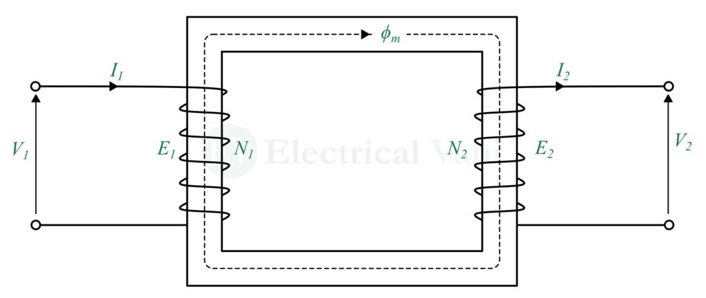
- N1 = Number of turns in the primary winding
- N2 = Number of turns in the secondary winding
- V1 = Applied voltage to the primary winding
- V2 = Output terminal voltage across the secondary winding
- E1 = EMF induced in the primary winding
- E2 = EMF induced in the secondary winding
- I1 = Primary winding current
- I2 = Secondary winding current
- ϕ = Magnetic flux in the core with ϕm as the maximum value
When an alternating voltage (sinusoidally varying) V1 having a frequency of f Hz is applied to the primary winding of this transformer, a sinusoidally varying magnetic flux ϕ will be set up in the magnetic core. This magnetic flux will be given by,
$$ϕ=ϕ_m sinωt$$
Where, ω = 2πf, is the angular frequency.
This magnetic flux links to the primary and secondary windings and induces an EMF according to Faraday’s law of electromagnetic induction. The instantaneous value of this induced EMF is given by,
$$e=-N \frac{dϕ}{dt}$$
Hence, the instantaneous value of EMF induced in the primary winding is given by,
$$e_1=-N_1 \frac{dϕ}{dt}$$
The instantaneous value of EMF induced in the secondary winding is given by,
$$e_2=-N_2 \frac{dϕ}{dt}$$
Let’s solve the expression for EMF e1, we get,
$$e_1=-N_1 \frac{dϕ}{dt}=-N_1 \frac{d}{dt} (ϕ_m sinωt )$$
$$⇒e_1=-N_1 ϕ_m ω cosωt$$
Since,
$$-cosθ=sin(θ-90°)$$
Therefore,
$$e_1=N_1 ϕ_m ω sin(ωt-90°)$$
$$e_1=2πfN_1 ϕ_m sin(2πft-90°)$$
From this equation, it is clear that the EMF induced in the primary winding of the transformer is also sinusoidally varying having a maximum value of Em1 which is given by,
$$E_{m1}=2πfN_1 ϕ_m$$
Therefore, the RMS value of the EMF induced in the primary winding is given by,
$$E_1=\frac{E_{m1}}{\sqrt{2}}=\frac{(2πfN_1 ϕ_m)}{\sqrt{2}}$$
$$⇒\bf{E_1=4.44fϕ_m N_1}$$
Since the EMF induced in the secondary winding is also produced by the same magnetic flux (ϕ). Therefore, the instantaneous value of EMF induced in the secondary winding is given by,
$$e_2=2πfN_2 ϕ_m sin(2πft-90°)$$
The RMS value of secondary winding EMF is given by,
$$\bf{E_2=4.44fϕ_m N_2}$$
In general, we can write,
$$\bf{E=4.44fϕ_m N}$$
This expression is referred to as EMF equation of the transformer.
Important Points
EMF Per Unit Frequency:
In practice, the supply frequency remains constant. For a given transformer, the values of ϕm and N are also constant. Thus,
$$\frac{E}{f}=4.44ϕ_m N=\text{Constant}$$
Hence, we can state that the EMF induced per unit frequency for a given transformer is a constant. However, it is different for primary and secondary winding depending on the number of turns.
EMF Per Turn:
For a given transformer, f and ϕm are constant, hence
$$E∝N$$
Therefore, for primary and secondary windings,
$$E_1∝N_1\text{ and }E_2∝N_2$$
$$⇒\frac{E_1}{E_2} =\frac{N_1}{N_2}$$
$$⇒\frac{E_1}{N_1} =\frac{E_2}{N_2}$$
This expression highlights that the induced EMFs per turn in the primary and secondary windings are equal for a given transformer.
Numerical Examples
Q. 1 – A single-phase transformer is connected to a 50 Hz supply and has a maximum flux in the core of 0.0216 Wb. If the primary winding has 500 turns and the secondary winding has 65 turns, then calculate the EMF induced in the primary and secondary windings of the transformer.
Solution – Given data,
$$f=50\text{ Hz}$$
$$ϕ_m=0.0216\text{ Wb}$$
$$N_1=500;N_2=65$$
Then, EMF induced in the primary winding is given by,
$$E_1=4.44fϕ_m N_1$$
$$⇒E_1=4.44×50×0.0216×500$$
$$\bf{∴E_1=2397.6\text{ V}}$$
The EMF induced in the secondary winding is given by,
$$E_2=4.44fϕ_m N_2$$
$$⇒E_2=4.44×50×0.0216×65$$
$$\bf{∴E_2=311.69\text{ V}}$$
Q. 2 – An 11000/440 V, 50 Hz single-phase ideal transformer is connected to an 11000 V, 50 Hz supply with secondary winding open. If the primary winding has 6000 turns, then calculate the maximum value of flux in the core.
Solution – Given
$$V_1=E_1=11000\text{ V (ideal transformer)}$$
$$f=50\text{ Hz}$$
$$N_1=6000$$
From the EMF equation of a transformer, we get,
$$ϕ_m=\frac{E_1}{(4.44fN_1 )}$$
$$⇒ϕ_m=\frac{11000}{(4.44×50×6000)}$$
$$\bf{∴ϕ_m=0.008258\text{ Wb}=8.258\text{ mWb}}$$
Conclusion
So, this is all about the EMF equation of a transformer. If you have any questions about this topic, kindly post in the comment section. I will answer shortly.