In digital electronics, there are two categories namely, basic logic gates and universal logic gates, in which all logic gates are classified. In this article, I will explain the universal logic gates in detail. Also, I will answer a most asked question in the field of electrical and electronics engineering “why NAND and NOR gates are universal logic gates”. In short, a type of logic gate that can implement any kind of Boolean function or expression without the need for any other type of logic gate is referred to as a universal logic gate. In digital electronics, there are two logic gates namely, NAND Gate and NOR Gate, that are considered universal logic gates. If you are interested in knowing why NAND and NOR gates are called universal logic gates, please read the complete article.

What is Universal Logic Gate?
A type of logic gate that can be used to implement any kind of logical expression or Boolean function without using any other type of logic gate is called a universal logic gate. In digital electronics, there are two universal gates namely,
- NAND Gate
- NOR Gate
The NAND and NOR gates are able to perform all three basic logic functions i.e., OR, AND, and NOT.
Now, let us explore these two types of universal gates in detail.
NAND Gate
A NAND gate is a type of universal logic gate that is a combination of two basic logic gates namely, AND gate and NOT gate. Therefore, it is also called a NOTed AND gate.
A NAND can have two or more inputs but only a single output. The output of the NAND gate is logic 0 or LOW, only when its all inputs are logic 1 or HIGH. For any other input combinations, the output of the NAND gate is logic 1 or HIGH.
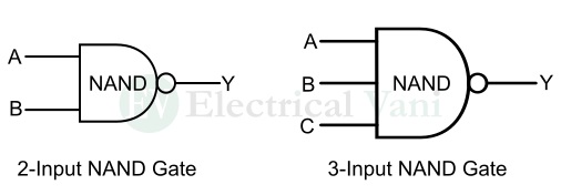
NAND Gate Symbol
The NAND gate symbols for two-inputs and three-inputs are shown in the following figure. However, the number of inputs to a NAND gate can be more than three depending on the application.
Truth Table of NAND Gate
The truth table for a two-input NAND gate is given below:
|
Inputs |
Output |
|
|
A |
B | Y |
|
0 |
0 |
1 |
|
0 |
1 |
1 |
| 1 | 0 |
1 |
| 1 | 1 |
0 |
The truth table for a three-input NAND gate is given below:
|
Inputs |
Output |
||
|
A |
B | C |
Y |
|
0 |
0 | 0 |
1 |
|
0 |
0 | 1 | 1 |
| 0 | 1 | 0 |
1 |
|
0 |
1 | 1 | 1 |
|
1 |
0 | 0 | 1 |
|
1 |
0 | 1 |
1 |
| 1 | 1 | 0 |
1 |
| 1 | 1 | 1 |
0 |
From these two truth tables, it is clear that the output of a NAND gate is logic 0, only when its all inputs are at logic 1. For all other input combinations, its output is logic 1.
NAND Gate Boolean Expression
The Boolean expression for the output of a NAND gate can be directly derived from its truth table.
The Boolean expression of a two-input NAND gate is given below:
$$Y=\overline{(A.B)}=(A.B)’$$
The Boolean expression of a three-input NAND gate is given below:
$$Y=\overline{(A.B.C)}=(A.B.C)’$$
This expression can be extended to any number of input variables.
NAND Gate Circuit Diagram
The switching circuit diagram of a two-input NAND gate is shown in the following figure.
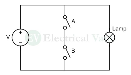
It consists of two switches, a power supply, and a lamp. The lamp will not glow, i.e. the output is logic 0, only when both the switches (i.e., A and B) are closed, i.e. at logic 1 level. If any of the switches A or B is open, i.e. logic 0, the lamp will glow, i.e. the output will be logic 1.
Similarly, we can implement the switching circuit of a NAND gate having three or more inputs by connecting three or more switches instead of two switches.
This is all about the NAND gate, let us now discuss another type of universal logic gate, i.e. NOR gate in detail.
NOR Gate
NOR gate is another type of universal gate that can be used to implement any kind of Boolean expression without the need for any other type of logic gate. It is a combination of two basic logic gates namely, OR gate and NOT gate. Hence, it is also called NOTed OR gate.
Similar to a NAND gate, a NOR gate can also have two or more inputs and one output. The output of a NOR gate is logic 1 or HIGH, only when its all inputs are logic 0 or LOW. For all other input combinations, the output of the NOR gate will be logic 0 or LOW.
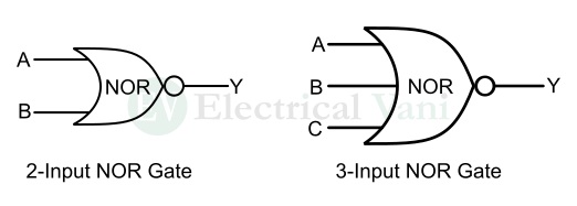
NOR Gate Symbol
The NOR gate symbols for two-inputs and three-inputs are shown in the following figure. However, the number of inputs to a NOR gate can be more than three depending on the circuit applications.
Truth Table of NOR Gate
The truth table of a NOR gate with two-input is given below:
|
Inputs |
Output | |
|
A |
B |
Y |
|
0 |
0 |
1 |
|
0 |
1 |
0 |
|
1 |
0 |
0 |
| 1 | 1 |
0 |
The truth table of a NOR gate with three inputs is given below:
|
Inputs |
Output |
||
|
A |
B | C |
Y |
|
0 |
0 | 0 | 1 |
| 0 | 0 | 1 |
0 |
|
0 |
1 | 0 | 0 |
| 0 | 1 | 1 |
0 |
|
1 |
0 | 0 | 0 |
| 1 | 0 | 1 |
0 |
|
1 |
1 | 0 | 0 |
| 1 | 1 | 1 |
0 |
Hence, from these truth tables of the NOR gate, it can be seen that the output of a NOR gate is logic 1 or HIGH, only when its all inputs are logic 0 or LOW. For all other input combinations, the output is logic 0 or LOW.
NOR Gate Boolean Expression
The Boolean expression of a two-input NOR gate is given below:
$$Y=\overline{(A+B)}=(A+B)’$$
The Boolean expression of a three-input NOR gate is given below:
$$Y=\overline{(A+B+C)}=(A+B+C)’$$
We can extend this Boolean expression of the NOR gate to any number of input variables.
NOR Gate Circuit Diagram
The switching circuit diagram of a two-input NOR gate is shown in the following figure. However, this circuit can be extended to any number of inputs by adding more switches.
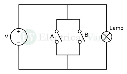
It consists of two switches A and B, a lamp, and a power supply. When both switches are open i.e., logic 0, the lamp will glow, i.e. the output is logic 1. But, if any of the switches is closed, i.e. logic 1, the lamp will turn off i.e., the output will be logic 0.
Hence, this is all about NAND and NOR gates in digital electronics. Now, let us know the answer to “why NAND and NOR are universal gates”.
Why NAND and NOR Gate are Universal?
As we mentioned above, the NAND and NOR gates individually can implement any kind of Boolean function without using any other type of logic gate. Also, they can perform all three basic logic operations i.e., AND, OR, and NOT. Therefore, they are called universal logic gates.
Conclusion
Hence, in this article, I have explained all about universal logic gates: NAND Gate and NOR Gate. In conclusion, a NAND gate is a universal gate that performs the inversion operation of an AND gate. On the other hand, a NOR gate is another type of universal gate that performs the inversion of an OR gate. Both NAND and NOR gates can have two or more inputs and one output.
FAQs on Universal Logic Gates
Q. 1 – Which gate is called a universal gate?
Ans. – NAND and NOR gates are called universal gates because they can implement any kind of logic function without using any other type of logic gates.
Q. 2 – Which is not a universal gate?
Ans. – Other than NAND and NOR gates, all logic gates are not universal logic gates. Examples of logic gates that are not universal gates are the AND gate, OR gate, NOT gate, XOR gate, and XNOR gate.
Q. 3 – How many universal gates are there?
Ans. – There are two universal gates namely, NAND gate and NOR gate. These two types of universal gates are explained in detail in the above sections of this article. Please read the complete article to know everything about these gates.
Q. 4 – What is NAND and NOR gate?
Ans. – A NAND gate is a combination of an AND gate and a NOT gate whose output is logic 0, only when all inputs are logic 1.
Whereas, a NOR gate is a combination of an OR gate and a NOT gate whose output is logic 1, only when its all inputs are logic 0.
Q. 5 – What is an example of a universal gate?
Ans. – Examples of universal gates are NAND gate and NOR gate.