In this article, I will explain the implementation of NOT gate using NAND gate. The NOT gate is a basic logic gate that acts as an inverter, whereas the NAND gate is a universal logic gate that acts as an inverted AND gate. Since the NAND gate is a universal logic gate, it can be used to realize any kind of logical function without the need for any other type of logic gate. Here, I will explain how we can use the NAND gate as an inverter or NOT gate. But before having a discussion on NOT gate implementation with NAND gate, let us first get an overview of NOT gate and NAND gate individually.

What is NOT Gate?
A NOT Gate, also called Inverter or Inverter Gate, is a type of basic logic gate used in digital electronics to perform complement operation.
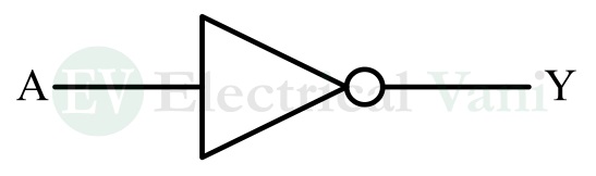
The NOT gate has only one input and one output. The output of the NOT gate is logic 0 or low when its input is logic 1 or high. The output is logic 1 or high, while its input is logic 0 or low.
Hence, it performs an inversion operation on the input and produces a complemented output.
The operation of the NOT gate is described in the following truth table.
| Input | Output |
| 0 | 1 |
| 1 | 0 |
The relationship between input and output of the NOT gate is given by its Boolean expression which is given below.
$$Y=\overline{A}$$
Here, the bar over the input variable A indicates the inversion or NOT operation.
What is NAND Gate?
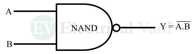
The NAND gate is a type of universal logic gate that can have two or more inputs and one output. The output of the NAND gate is logic 0 when all its inputs are logic 1. For rest input combinations, the output of the NAND gate is logic 1.
The logical operation of a two-input NAND gate is described in the truth table below.
| Inputs | Output | |
| A | B | Y |
| 0 | 0 | 1 |
| 0 | 1 | 1 |
| 1 | 0 | 1 |
| 1 | 1 | 0 |
The relationship between inputs and output of the NAND gate is given by its Boolean function which is given below.
$$Y=\overline{AB}$$
Here, the bar over the logical product of inputs AB is indicating the inverted AND operation.
Hence, this is all about the basics of NOT gate and NAND gate. Let us now discuss how to implement the NOT gate using the NAND gate only.
Implement NOT Gate using NAND Gate
To implement the NOT gate operation using NAND gates, first, we have to derive the relationship between NOT gate logic and NAND gate logic. The output function of the NOT gate in terms of NAND gate output is given below.
The NOT gate has only one input and its output is,
$$Y=\overline{A}$$
But the NAND gate can have a minimum of two inputs i.e., its output is,
$$Y=\overline{A.B}$$
Let us set both inputs of the NAND gate to the same logical input i.e., A = B = A. Then, the output of the NAND gate will be,
$$Y=\overline{A.A}=\overline{A}$$
This is equivalent to the output of the NOT gate. Hence, we can use the NAND gate by joining all its input lines together and applying the same input.
Circuit Diagram of NOT Gate using NAND Gate:
The circuit diagram of the NOR gate using the NAND gate is shown in the following figure.
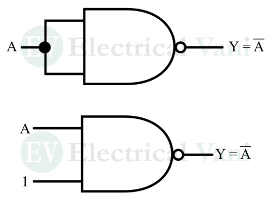
In this circuit, we have connected both inputs of the NAND gate together and applied a common input to obtain the inverter output at the output line.
In the second circuit, we have connected one input to logic 1, and input A is connected to another input line. This also acts as the NOT gate, as follows.
$$Y=\overline{A.1}=\overline{A}$$
Conclusion
Hence, in this article, I have explained how to implement the NOT gate using the NAND gate. The implementation of the NOT gate with the NAND gate is explained above with the help of a circuit diagram.
If you have any queries related to this topic, please let me know in the comment section.