In this article, I will explain the XOR Gate and XNOR Gate in detail. In digital electronics, there are several types of logic gates such as AND gate, OR gate, NOT gate, NOR gate, and NAND gate. Similarly, there are two other logic gates i.e., X-OR gate and X-NOR gate. Both these logic gates are called derived logic gates. Also, these two logic gates can take only two inputs unlike all other types of logic gates that can take more than two inputs.
In this article, I will cover definitions, truth tables, symbols, Boolean expressions, and applications of XOR and XNOR gates.
What is XOR Gate?
An XOR gate is a type of derived logic gate that can have two inputs and one output. The output of the XOR gate is in logic 1 or high state when one of its two inputs is in logic 1 or high state. The output of the XOR gate is in logic 0 or low state when both inputs are either logic 0 or logic 1.
Therefore, the XOR gate produces a logic 1 or high output only when both inputs are dissimilar. For this reason, it is also known as an inequality detector. The XOR gate is also known as the Exclusive-OR gate or Ex-OR gate.
It is important to note here, that there is no XOR gate having three or more inputs.
XOR Gate Symbol
The logic symbol of an XOR gate is shown in the following figure.
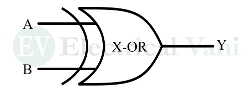
Here, A and B are the input variables and Y is the output variable.
XOR Gate Truth Table
The truth table is a table showing the relationship between inputs and output of the logic gate. The truth table of the XOR gate is given below:
|
Inputs |
Output | |
| A | B |
Y |
|
0 |
0 | 0 |
| 0 | 1 |
1 |
|
1 |
0 | 1 |
| 1 | 1 |
0 |
From this truth table, it is clear that the output of an XOR gate is logic 1 or higher, only when both inputs are dissimilar. When both inputs are the same, the output is logic 0 or low.
XOR Gate Boolean Expression
Boolean expression is a logical function that represents the relationship between inputs and output of a logic circuit. The Boolean expression of the XOR gate can be derived from its truth table as follows.
$$Y=A’B+AB’=\overline{A}B+A\overline{B}$$
This can also be written as,
$$Y=A⊕B$$
Where the symbol “⨁” represents the exclusive OR operation.
This is all about XOR gate in digital electronics. Let us now explore the concepts of the XNOR gate.
What is XNOR Gate?
As the name implies, XNOR gate is a combination of XOR gate and NOT gate. Similar to the XOR gate, the XNOR gate is also a derived logic gate having two inputs and one output. The output of the XNOR gate is in logic 1 or high state, only when both the inputs are either logic 0 or low or logic 1 or high. If the two inputs are such that one is logic 0 and the other is logic 1, then the output of the XNOR gate is logic 0.
Since the output of the XNOR gate is logic 1 or high when both the inputs are similar. Hence, it is also called an equality detector.
It is also known as Exclusive-NOR gate or Ex-NOR gate. It is also important to note that three or more input XNOR gate does not exist.
XNOR Gate Symbol
The logic symbol of the XNOR gate is shown in the following figure.
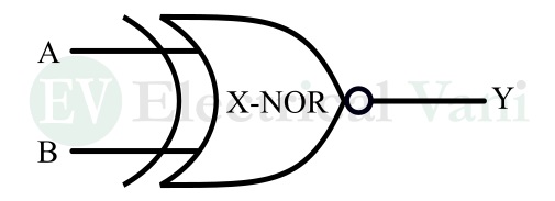
Here, A and B are the input variables and Y is the output variable.
XNOR Gate Truth Table
The truth table of the XNOR gate is given below:
|
Inputs |
Output | |
| A | B |
Y |
|
0 |
0 | 1 |
| 0 | 1 |
0 |
|
1 |
0 | 0 |
| 1 | 1 |
1 |
From this truth table, it is clear that the output of the X-NOR gate is logic 1, only when both the inputs are similar.
XNOR Gate Boolean Expression
The Boolean expression of the XNOR gate can be derived from its truth table as follows.
$$Y=A’B’+AB=\overline{A}\overline{B}+AB$$
This can also be written as,
$$Y=A⊙B$$
Here, the symbol “⊙” represents the Exclusive NOR operations.
Application of XOR and XNOR Gate
The XOR and XNOR gates are widely used in digital circuits and system design. Some key examples of applications of XOR and XNOR gates are as follows:
- To design comparators.
- To implement binary adders and subtractors.
- To design switchable buffers and inverters.
- To design parity checkers and generators.
- To implement circuits used in error detection in digital information.
Conclusion
In this article, I have explained the XOR and XNOR gates in detail. In conclusion, the XOR gate is a two-input logic gate whose output is logic 1 when both of its inputs are dissimilar. On the other hand, the XNOR gate is a two-input logic gate whose output is logic 1 when both of its inputs are similar. These gates are widely used in implementing different types of digital systems such as comparators, error detectors, arithmetic circuits, and more.
If you have any queries related to the topic, please let me know in the comment section. I will answer shortly.