In this chapter, we will learn about electrical safety in solar plants in detail. Electrical safety is a very important requirement in the design and operation of a solar power plant. It becomes more crucial in case of a utility-scale solar power plant because it contains very large DC and AC electrical systems, ranging from PV strings operating at high DC voltage to medium- and high- AC voltages.
It is also important to note that a solar plant has one important characteristic that makes its electrical safety different from other conventional electrical systems –
A PV module produces electrical voltage whenever it receives sufficient light.
Therefore, turning off an inverter or opening the AC circuit breaker does not necessarily make the PV array electrically safe. The DC cables between the PV modules and inverter may remain energized during daylight. Solar plant developers identify electric shock and arc-flash hazards as important risks associated with solar PV systems.
Electrical Hazards in a Solar Plant
The following are some major electrical hazards associated with solar power plants –
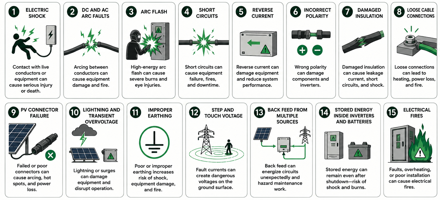
These risks exist throughout the complete solar plant. Therefore, the electrical safety should be addressed at every stage of the plant.
DC Arc Hazard & Safety
|
Reasons of DC Arc Hazard |
Practices to DC Arcing |
|
|
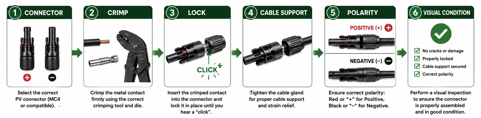
PV Connector Safety
PV connectors are small components in solar plants, but their failure can result in significant safety and reliability issues.
Solar developers have identified connector failures associated with arc, ground, insulation and over-temperature faults, system shutdown and fire.
PV Connector installation mistakes –
- Mixing connectors from different manufacturers
- Incorrect crimping
- Incomplete connector locking
- Poor cable stripping
- Using damaged connectors
- Pulling cables directly through connectors
- Leaving connectors exposed to standing water
- Excessive mechanical stress
To avoid these issues, the PV connector should be selected and installed as per the module specifications and connector manufacturer’s requirements.
Points to check during commissioning of the solar plant –
Cable Installation Safety
|
Environmental Conditions |
Parameters for Cable Selection |
Things to Avoid |
|
|
|
Cable Termination and Torque
Loose electrical connections are a common source of overheating and sometimes fire.
The heat generated at a cable joint can be given by,
$$P_{loss}=I^2 R$$
Where, Ploss is the power converted into heat, I is the current, and R is the contact resistance.
From this expression, it is clear that a small increase in contact resistance can therefore result in significant heating at high current.
Best Practices for Cable Termination –
- Use the correct lug.
- Use the correct crimping tool.
- Follow the manufacturer’s stripping length.
- Apply the specified torque.
- Mark completed torque checks.
- Maintain a torque record.
- Perform thermal inspection during operation.
Thus, do not tighten electrical terminals by guesswork.
Thermal Imaging (Thermography)
Thermal imaging is very useful for identifying developing electrical issues in systems before they become failures.
Thermography should be performed under suitable operating conditions and interpreted by competent personnel.
|
Sections to Check for Abnormal Temperature Rise |
Abnormal Hot Spot May Indicate |
|
|
Earthing and Equipotential Bonding
Earthing is one of the most important electrical safety systems in a solar plant. In solar plants, the earthing system must provide an appropriate path for fault current and control dangerous potential differences.
|
Equipment Requiring Appropriate Bonding/Earthing |
Parameters to Consider For Earthing Design |
|
|
Touch and Step Voltage
An earth fault can cause the potential of metallic equipment and surrounding ground to rise.
There are two important safety parameters –
- Touch Voltage – The voltage difference between an accessible metallic object and the point where a person is standing.
- Step Voltage – The voltage difference between two points on the ground separated by a person’s step.
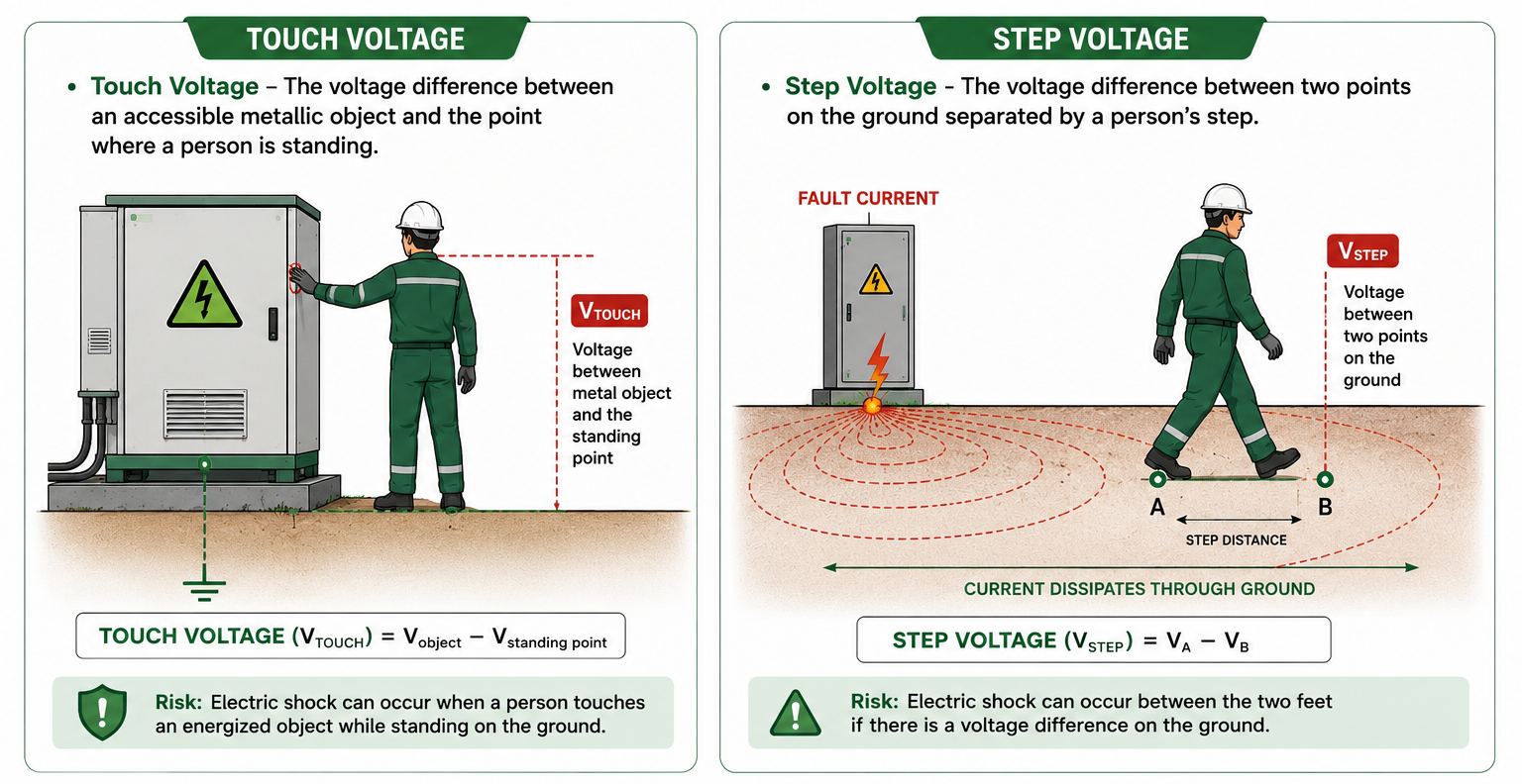
These two safety parameters are important around –
- Transformers
- HT switchgear
- Substations
- Earthing grids
- Lightning down-conductor locations
Hence, the substation earthing system should be designed and verified for acceptable touch and step voltage conditions rather than relying only on a measured earth resistance value.
Lightning and Surge Protection
A utility-scale solar power plant occupies a large open area and can be exposed to lightning.
In a solar plant, the following equipment can be damaged due to lightning and switching surges –
- PV modules
- Inverters
- Transformers
- SCADA equipment
- Weather stations
- Communication equipment
- DC cables
- AC equipment
A properly coordinated protection system in solar plant may consist of –
Lightning Protection System + Earthing System + Surge Protective Devices + Equipotential Bonding
SPDs should be selected according to the system voltage, earthing configuration, location and equipment requirements.
The purpose is not only to install an SPD at every possible location. But the complete surge-protection system should be coordinated.
Overcurrent and Short-Circuit Protection
Protection devices must be capable of safely interrupting the expected fault current.
Depending on the system, protection may include the following protection devices –
- String fuses
- DC fuses
- DC circuit breakers
- MCCBs
- ACBs
- HT circuit breakers
- Protection relays
- Earth-fault protection
For a protective device,
$$I_{breaking} \geq I_{fault}$$
Where,
- Ibreaking = Interrupting capacity of the protection device
- Ifault = Expected fault current
Protection should also be coordinated so that the smallest practical portion of the plant is disconnected during a fault.
Inverter Safety
The inverter is a critical interface between the DC and AC systems.
|
Potential Hazards Associated to Inverter |
Do’s Before Working Inside Inverter |
|
|
Note – Never open an inverter simply because its display is OFF.
Transformer and HT Equipment Safety
Transformer yards and HT switchgear represent a major electrical hazard because of their high operating and fault voltages.
The following safety provisions to be followed –
- Proper protection relays
- Earth-fault protection
- Overcurrent protection
- Differential protection where applicable
- Transformer temperature protection
- Surge protection
- Proper earthing
- Interlocking
- Fencing
- Warning signs
- Safe electrical clearances
- Restricted access
For oil-filled transformers, fire protection and appropriate separation should also be considered.
Arc Flash Safety
Arc flash can produce –
- Extreme heat
- Molten metal
- Pressure waves
- Intense light
- Burns
- Hearing damage
- Eye injuries
Therefore, arc-flash risk should be assessed for relevant electrical equipment.
Lockout/Tagout (LOTO)
LOTO is one of the most practical safety controls during maintenance.
The basic principle of LOTO is –
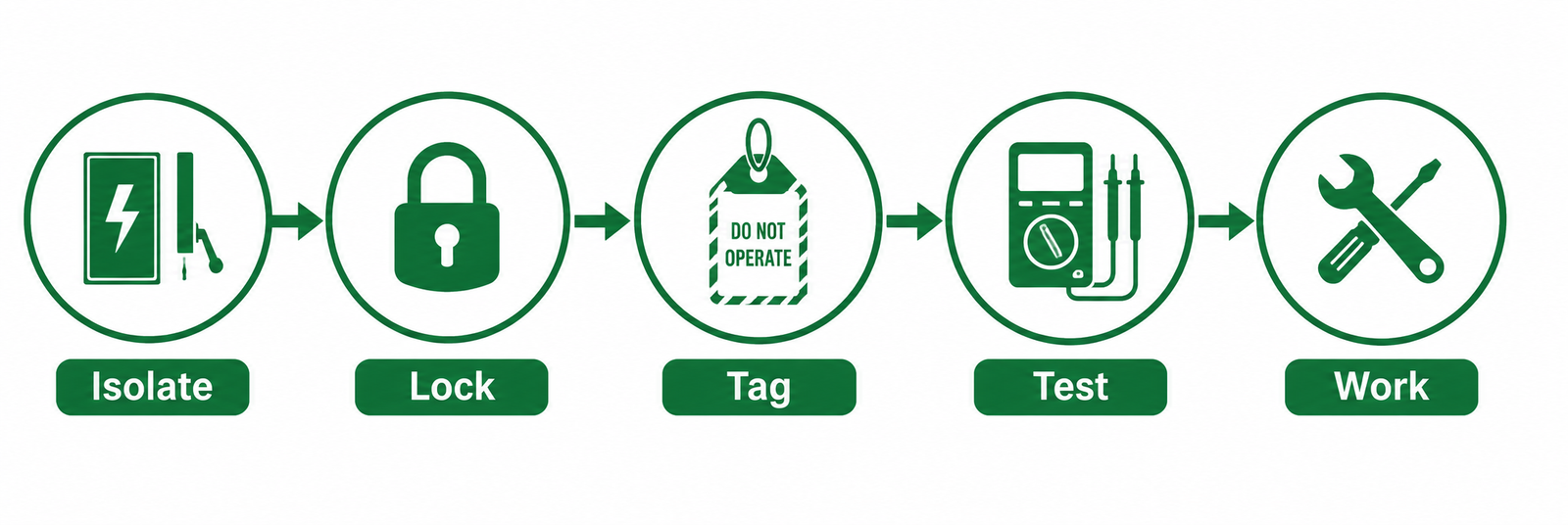
A typical LOTO procedure is explained here –
- Step 1 – Identify the equipment.
- Step 2 – Identify all energy sources.
- Step 3 – Shut down the equipment.
- Step 4 – Isolate every applicable energy source.
- Step 5 – Apply personal locks.
- Step 6 – Attach warning tags.
- Step 7 – Verify absence of voltage.
- Step 8 – Perform the work.
- Step 9 – Inspect the equipment before re-energization.
- Step 10 – Remove locks according to the approved procedure.
- Step 11 – Restore the system.
Test Before Touch
One of the simplest and most important safety rules in electrical work is –
Never assume that equipment is de-energized.
After isolation, verify the absence of voltage using an appropriately rated test instrument and the approved testing procedure.
For HT equipment, the procedure may also require approved voltage detection and application of earths before work.
The tester itself should be verified according to the applicable safe-testing procedure.
Electrical Safety During Commissioning
In solar plants, commissioning is one of the highest-risk stages because systems are energized for the first time.
Before energization, the following important practical checks should be made –
|
DC Side |
AC Side |
Overall System |
|
|
|
Emergency Shutdown
Every solar plant should have a clearly defined emergency shutdown philosophy.
|
Possible Emergencies |
Points to be Defined in Emergency Procedure |
|
|
Also, the emergency procedure should be available to operators and emergency-response personnel.
Electrical Safety During Maintenance
|
Daily/Operational Checks |
Periodic Inspection |
Preventive Testing |
|
|
|
The maintenance interval should be based on the equipment manufacturer’s recommendations, plant experience, environmental conditions and applicable standards.
Safety Labels and Identification
Clear identification can prevent incorrect switching. Therefore, equipment should have durable labels identifying the following –
- Equipment number
- Voltage level
- Circuit number
- DC/AC designation
- Isolation points
- High-voltage warning
- Emergency shutdown
- Transformer identification
- Cable identification
- Earthing points
Also, PV systems should clearly communicate that the DC array may remain energized in daylight.
Labels should be suitable for the site’s outdoor environmental conditions.
Practical & Safe Design Checklist
Before finalizing the electrical design of a solar plant, the design engineer should verify the following points –
|
PV DC System |
AC System | Earthing |
Maintenance Safety |
|
|
|
|
Common Safety Mistakes to Avoid in Solar Plants
Mistake 1 – Inverter OFF means no voltage.
- The PV array can remain energized.
Mistake 2 – The connector fits, so it is compatible.
- Physical fit does not automatically guarantee electrical compatibility.
Mistake 3 – Earth resistance is low, so the earthing system is safe.
- Not necessarily. Touch and step voltage and fault-current performance must also be considered.
Mistake 4 – The cable is carrying normal current, so the connection is safe.
- Not necessarily. A loose connection can create localized heating even under normal operating current.
Mistake 5 – PPE (Personal Protective Equipment) will protect the worker.
- PPE is only the last layer of protection. Isolation and engineering controls should come first.
Mistake 6 – A small hot spot can be ignored.
- A hot connector or termination may be an early indication of a developing electrical fault.