This article provides the major technical and operational Differences between a Power Transformer and an Inverter Duty Transformer i.e., Power Transformer Vs Inverter Duty Transformer.
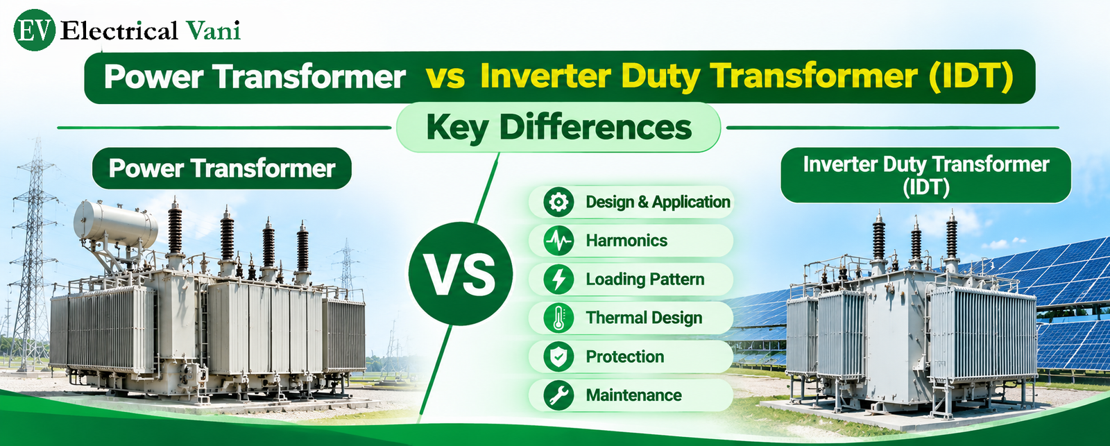
Difference between Power Transformer and IDT
The following table highlights major differences between a power transformer and an inverter duty transformer –
|
Comparison Factor |
Power Transformer (PTR) |
Inverter Duty Transformer (IDT) |
| Main Application | PTR is mainly used in power generation, transmission, and industrial electrical systems. | IDT is primarily used in solar PV plants or other inverter-based generation systems. |
| Input Supply | PTR receives conventional AC power from generators or electrical grids. | IDT receives AC power produced by inverters using power electronic switching devices like IGBT. |
| Primary Function | PTR steps up or steps down voltage for transmission applications. | IDT generally steps up inverter output voltage to the medium-voltage level for power evacuation. |
| Input Waveform | PTR is primarily designed for sinusoidal AC voltage and current conditions. | IDTs are designed considering inverter-generated waveforms and their harmonic characteristics. |
| Harmonic Handling | PTR is designed according to specified network harmonic conditions. | IDT is specifically designed for inverter-generated harmonics and associated additional losses. |
| Winding Design | PTR windings are designed based on rated voltage, current, impedance and conventional loading conditions. | IDT may require special design considerations to withstand additional harmonic-related winding and stray losses. |
| Core Design | PTR core is designed to maintain acceptable flux density and minimize core losses under rated operating conditions. | IDT core is designed considering inverter operating characteristics while maintaining acceptable core losses and thermal performance. |
| Insulation Requirements | PTR insulation is designed according to system voltage, impulse withstand level and applicable standards. | IDT also considers inverter-related voltage transients and electrical stresses as specified for the application. |
| Loading Pattern | PTR’s loading depends on grid demand, generation and connected electrical loads. | IDT’s loading mainly depends on solar irradiance, weather conditions, and inverter availability. |
| Temperature Rise | PTR is evaluated based on rated loading, losses, cooling arrangement and ambient temperature. | IDT is evaluated considering variable inverter loading, harmonic-related losses and ambient temperature. |
| Cooling Arrangement | PTR generally uses ONAN, ONAF, OFAF, ODAF and other specified cooling arrangements. | IDT commonly uses ONAN cooling in solar plants, depending on transformer rating and design requirements. |
| Voltage Transformation | PTR can be step-up or step-down depending on the application, such as 33/220 kV or 440/132 kV. | IDT is generally step-up transformer, such as 0.8/33 kV or 0.69/33 kV. |
| Vector Group | Vector group in PTR is selected according to grid requirements, earthing arrangements and protection coordination. | IDT’s vector group is selected according to inverter configuration, grounding philosophy and plant protection requirements. |
| Protection System | PTR uses differential, REF, Buchholz, overcurrent, earth-fault and temperature protections as applicable. | IDT also uses similar transformer protections as PTR, coordinated with inverter protection and plant electrical protection systems. |
| Maintenance Requirements | PTR requires oil testing, DGA, BDV, IR, winding resistance, TTR, bushing and cooling system inspections. | IDT also requires similar transformer maintenance, with additional attention to inverter output harmonics, loading profile and temperature trends. |