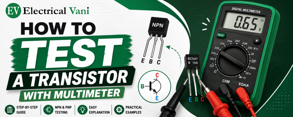
In this chapter, we will discuss how to test a transistor using a Digital Multimeter in a simple step-by-step process.
A transistor is one of the most important semiconductor devices used in electronic circuits for switching and amplification purposes. However, before using a transistor in any electronic circuit, it is very important to check whether it is in good working condition or not.
The simplest method to test an NPN/PNP transistor is by using a Digital Multimeter (DMM). Since a Bipolar Junction Transistor (BJT) consists of two PN junctions, its condition can be verified by checking the forward and reverse bias characteristics of these two PN junctions.
Principle of BJT Transistor Testing
A Bipolar Junction Transistor (BJT) is made up of two semiconductor PN junctions, namely –
- Base-Emitter (BE) Junction
- Base-Collector (BC) Junction
These junctions behave like simple PN junction diodes.
In case of a PN junction diode –
- Forward Biased (Positive probe connected to the P-type region and Negative probe connected to the N-type region), the junction conducts electricity and the multimeter displays a voltage drop.
- Reverse Biased, the junction blocks current, and the multimeter displays OL (Open Loop) or no continuity.
By testing both junctions in forward and reverse bias, we can determine whether the transistor is in good working condition or faulty.
How to Test an NPN Transistor Using a Digital Multimeter
We can follow the steps given below to test the health of an NPN transistor (same can be repeated for a PNP transistor with reversed polarity) –
Step 1: Set the Digital Multimeter

First, set the digital multimeter to Diode Test Mode. If diode mode is unavailable, we can also use the continuity mode.
Step 2: Test the Base-Emitter Junction (Forward Bias)
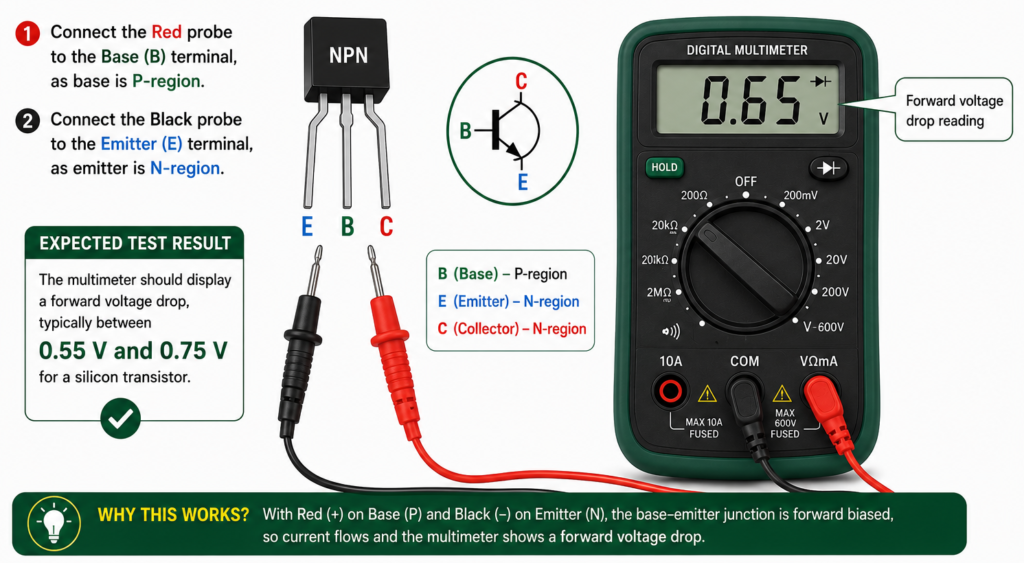
- Connect the Red probe to the Base (B) terminal, as base is P-region.
- Connect the Black probe to the Emitter (E) terminal, as emitter is N-region.
Expected Test Result:
The multimeter should display a forward voltage drop, typically between 0.55 V and 0.75 V for a silicon transistor.
Step 3: Test the Base-Collector Junction (Forward Bias)
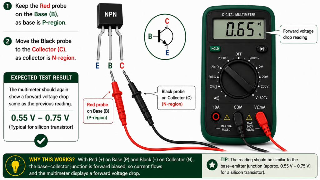
- Keep the Red probe on the Base (B), as base is P-region.
- Move the Black probe to the Collector (C), as collector is N-region.
Expected Test Result:
The multimeter should again show a forward voltage drop same as the previous reading.
Step 4: Test the Base-Emitter Junction (Reverse Bias)
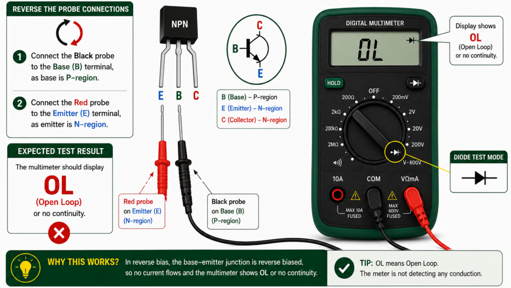
Reverse the probe connections, i.e.,
- Connect the Black probe to the Base (B) terminal.
- Connect the Red probe to the Emitter (E) terminal.
Expected Test Result:
The multimeter should display OL (Open Loop) or no continuity.
Step 5: Test the Base-Collector Junction (Reverse Bias)
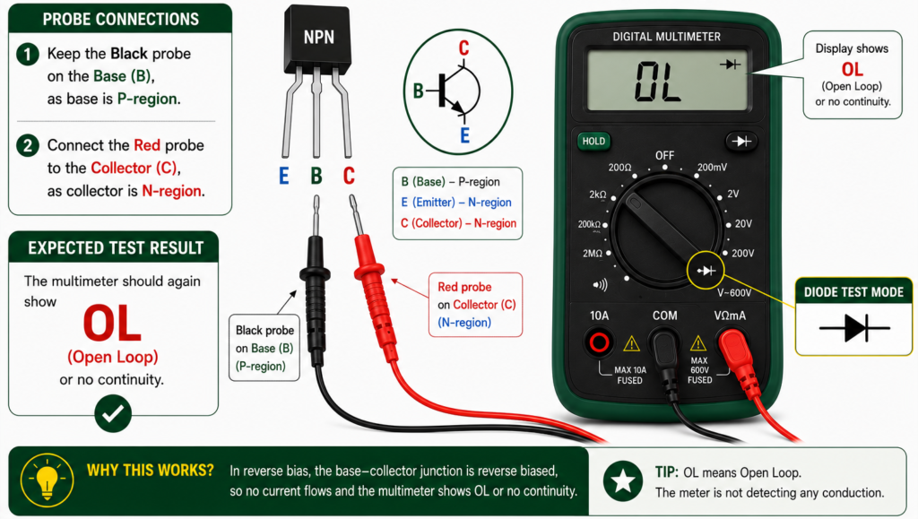
- Keep the Black probe on the Base (B).
- Connect the Red probe to the Collector (C).
Expected Test Result:
The multimeter should again show OL or no continuity.
Step 6: Test the Collector-Emitter Conductivity
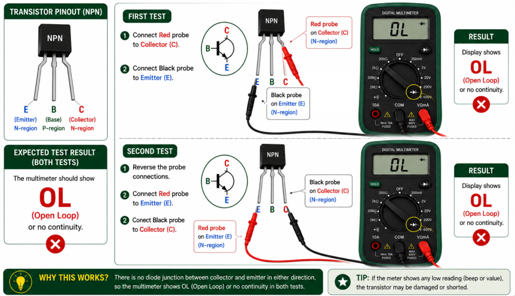
Next, we check the collector and emitter terminals directly.
First Test
- Connect Red probe to Collector (C).
- Connect Black probe to Emitter (E).
Expected Test Result:
The multimeter should show OL or no continuity.
Second Test
Reverse the probe connections i.e.,
- Connect Red probe to Emitter (E).
- Connect Black probe to Collector (C).
Expected Test Result:
The multimeter reading should remain OL or no continuity.
Multimeter Readings for a Healthy NPN Transistor
If the NPN transistor is in healthy condition, then it should show the following readings in multimeter tests –
| Test Condition | Expected DMM Reading |
| Terminal (Probe) → Terminal (Probe) | |
| Base (+) → Emitter (−) | 0.55–0.75 V |
| Base (+) → Collector (−) | 0.55–0.75 V |
| Base (−) → Emitter (+) | OL |
| Base (−) → Collector (+) | OL |
| Collector ↔ Emitter (Both Directions) | OL |
Identification of Faulty Transistor
A transistor is considered faulty if we observe any of the following conditions –
- The multimeter shows OL/no continuity in both forward and reverse directions of a junction.
- The multimeter indicates continuity in both directions.
- The collector and emitter terminals show continuity without any base connection.
- The forward voltage drop is significantly different from the normal range (approximately 0.55–0.75 V for silicon BJTs).
Testing of PNP Transistor Using DMM
The testing procedure for a PNP transistor is also the same as for an NPN transistor, but the probe polarity is reversed. Hence, for a PNP transistor –
- Black probe is connected to the Base during forward-bias testing.
- Red probe is connected to the Emitter or Collector.
The expected forward voltage drops and reverse-bias readings remain the same.